The ultimate 3D printer Z probe
I really got tired of the Anycubic Kossel Z probe.
The original probe is a little microswitch on a L-shaped stand, which magnetically attaches to a spot next to the printer nozzle. So you have to place it, and connect the probe wire manually whenever a probe operation is done (to calibrate the delta columns, or probe the bed, etc.). Connecting and disconnecting the cable is difficult as the cables are short and kind of tight. So the first improvement I made was a magnetic connector using pogo pins. This way there is nothing to connect/disconnect. That worked well enough but did not fix all the other issues with such a probe:
- manual install. Sometimes you forget something. Like, to uninstall the probe and print, which causes a head crash. messing all the calibration and breaking things…
- not very precise, it wobbles a tiny bit on the head
- since it moves, the Z-probe offset has to be periodically adjusted, which is long and tedious
- a microswitch is not the most repeatable contact sensor.
All these are really a pain and a waste of time, specially for a remote-operated printer where I have to run down to the garage to baby-sit any Z probe or calibration procedure.
So I set to create the ultimate 3D printer Z-probe (for me) with the following criterias:
- It must add zero mass to the print head (fast moves)
- must be fast and sensitive (quick reactions)
- must have no offset to the nozzle
- must self configure if possible, or just once at installation
- must deploy automatically
- would ideally involve zero extra mechanical elements like solenoids, servo motor arms, etc.
- can be entirely managed remotely if any full reset or configuration is ever required
- ideally be entirely solid-state
- must be cheap in materials
- must be easy to install
The first deduction from these criterias is that the sensing mechanism will have to be located in the printer bed. A common way to do that is by using the printbed and nozzle themselves as elements of a switch. When the nozzle makes contact with the bed, it closes a circuit that signals touchdown.
I do not like that because the whole machine becomes part of a circuit, which can cause a whole lot of various problems with leaks, bad contacts and more. Further, it would not work for me as I long ago replaced the original aluminum bed with a glass bed, which is non-conductive obviously. Using capacitance might be possible, but I suspect it would easily be affected by objects on or around the print bed.
A mechanical switch under the bed: unacceptable, as it implies the bed has to move a bit, thus a locking/unlocking mechanism would be required. Pressure sensors such as resistive sensors are kind of expensive, and piezo sensors require high voltages and uncommon electronic interfaces. What is (realistically) left: strain gauges, which seem pretty ideal to me
- no deformation (or so small it does not matter)
- very sensitive (in the 1/10000 of newton range)
- readily available and cheap
- amplifier and interface circuit are well known, documented and very cheap.
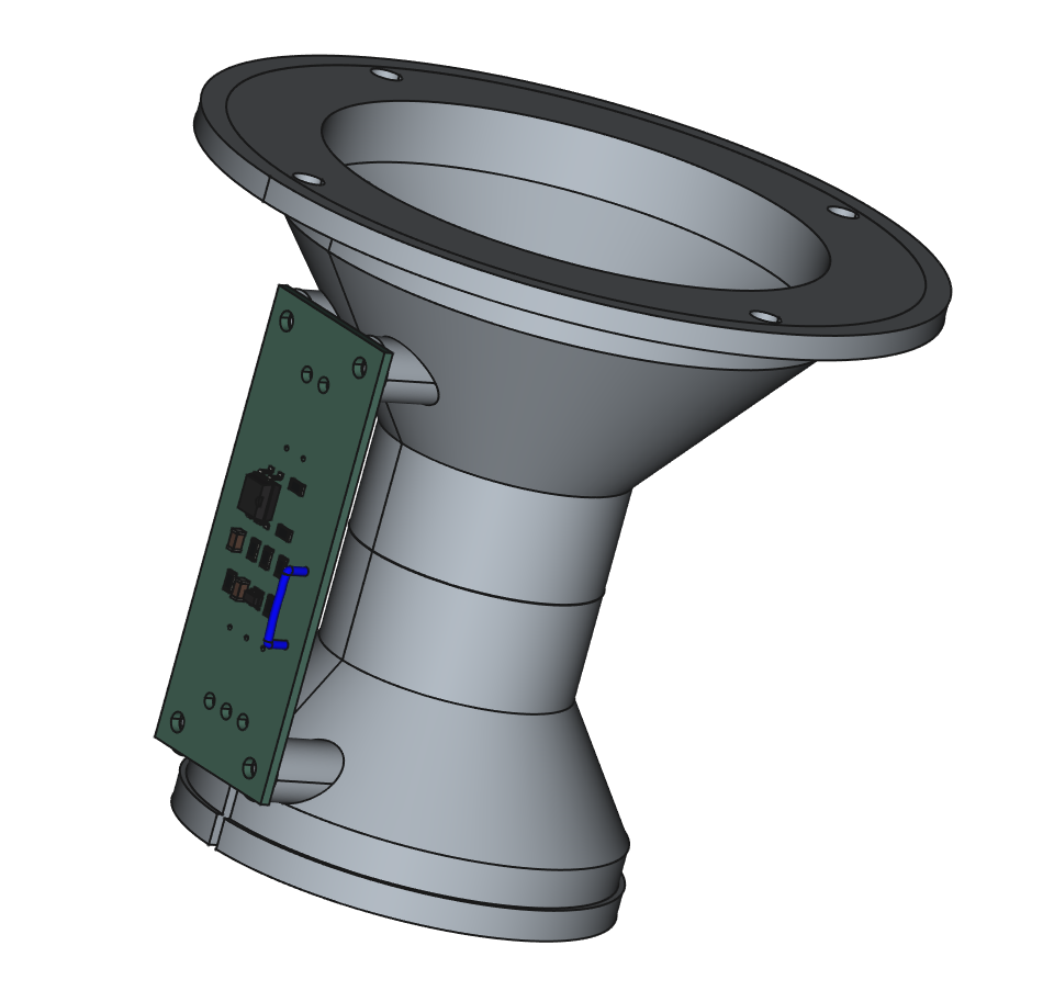
The idea would be to transform the old aluminum printbed into a custom strain sensing platform and apply it to the back of the glass printbed.
First tests
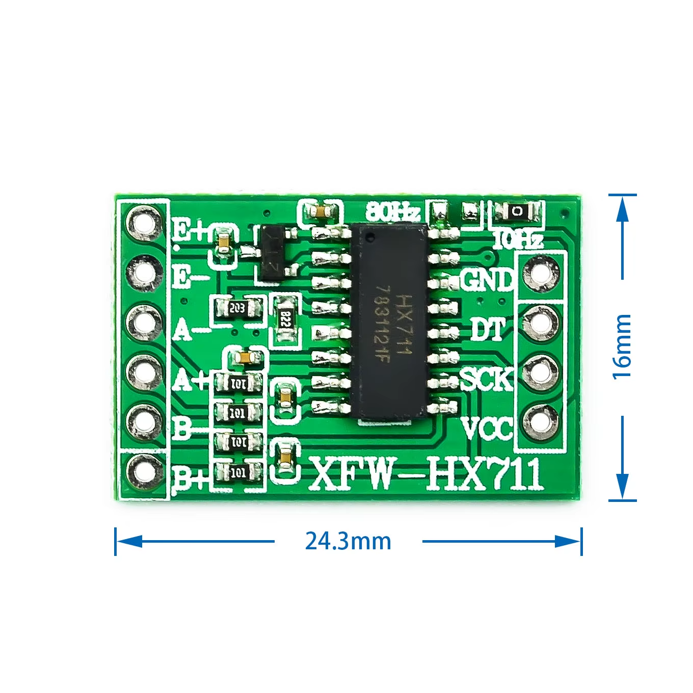
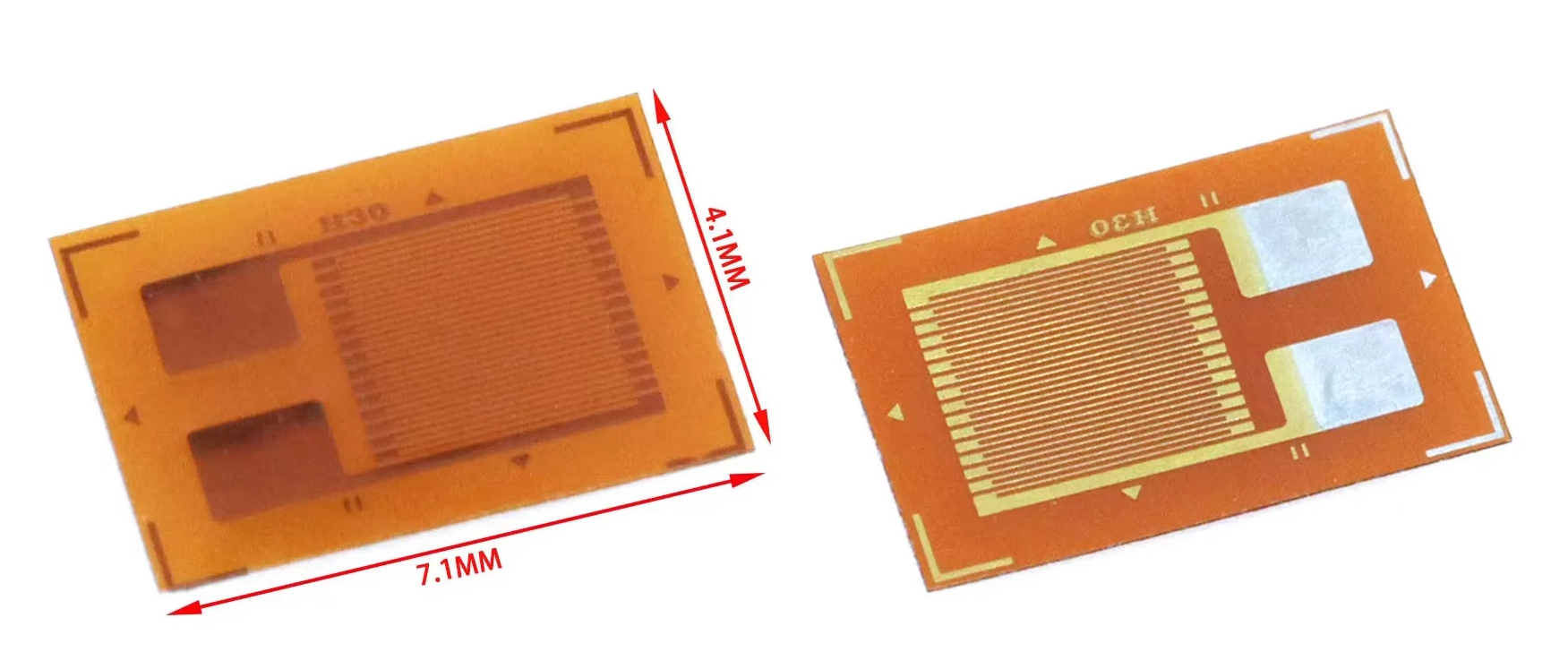
To experiment with the strain gauges and interfacing I ordered from Aliexpress small gauges (about 30 cent each) and HX711 interface module (70 cents).
I picked the HX711 module that has the pads to select the update rate, as the default 10Hz rate is a little low and 80Hz will do much better.
Those strain gauges are really small ! it will be great for this application
Next I made a test load cell on a 4mm thick flat bar of aluminum
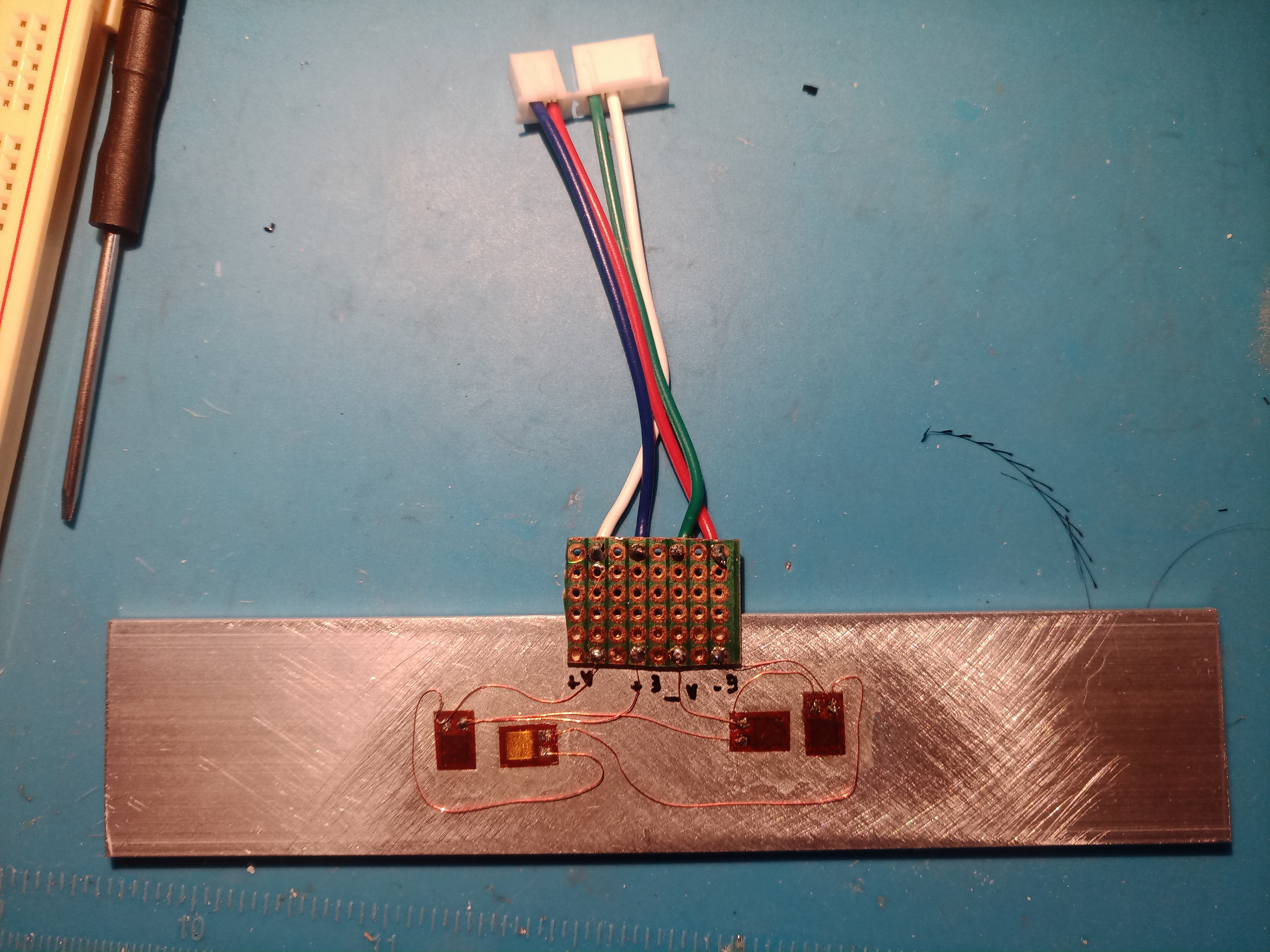
This taught me that soldering and laying out such thin magnet wire is quite annoying and difficult. It tends to lift, not stay in place, it is very difficult to remove the insulating laquer properly, it is so thin it tends to melt on the tip of the soldering iron. And it’s very easy to overheat the strain sensor and lift the pads while soldering. I later came up with a much better solution.
To drive the HX711, I was going to use an stm8 board but laziness won: there are plenty of arduino libraries to communicate with the HX711, so I used an arduino pro mini clone that I already had as well instead. Since the pro mini has no usb/serial converter, it’s great to hook up directly to the serial pins on the OrangePiOne controlling the printer with octoprint. This way the octoprint Pi board powers the Arduino, can control/configure it over the serial port, and also program the firmware on it.
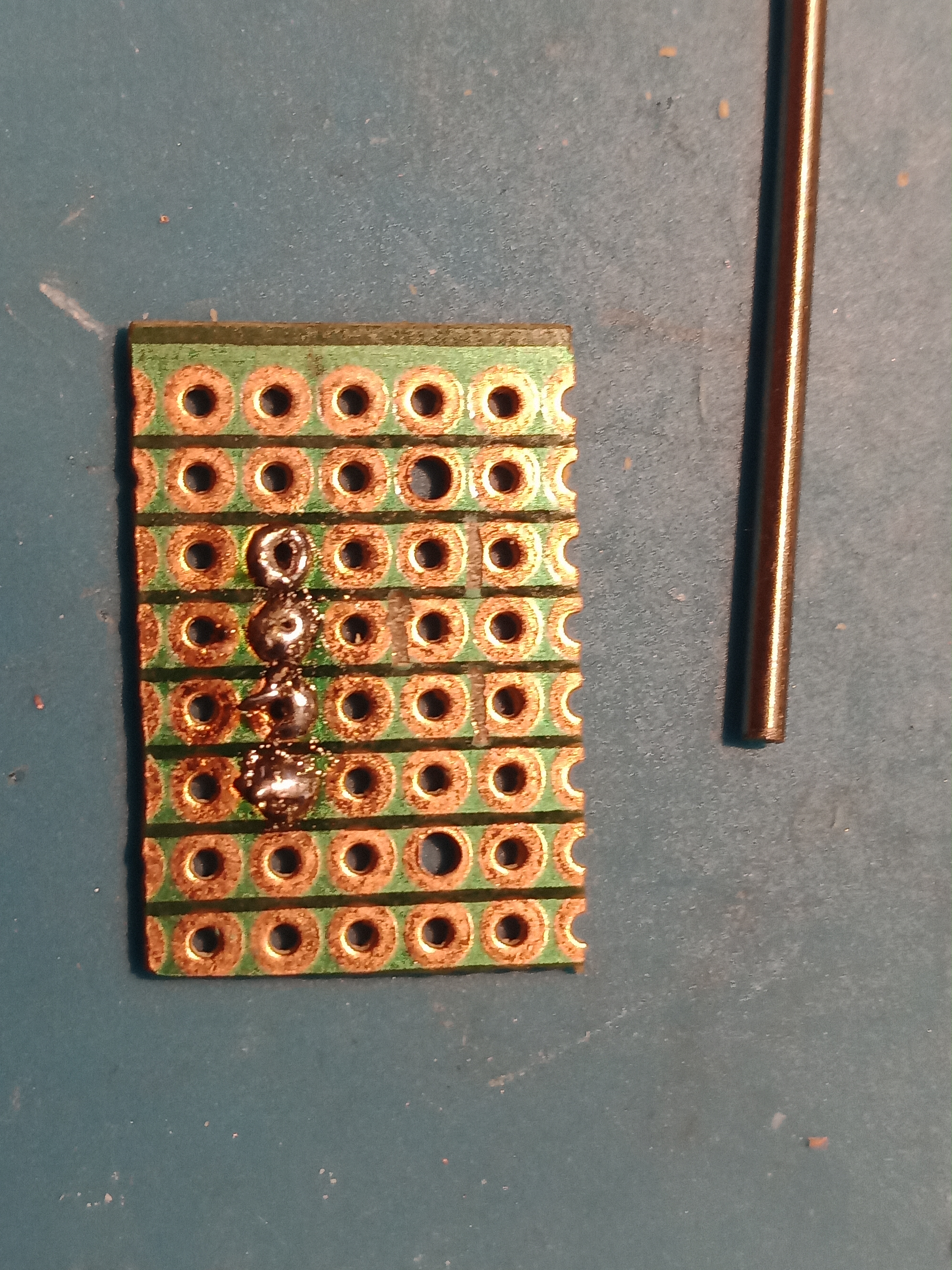
I whipped a quick prototype on veroboard
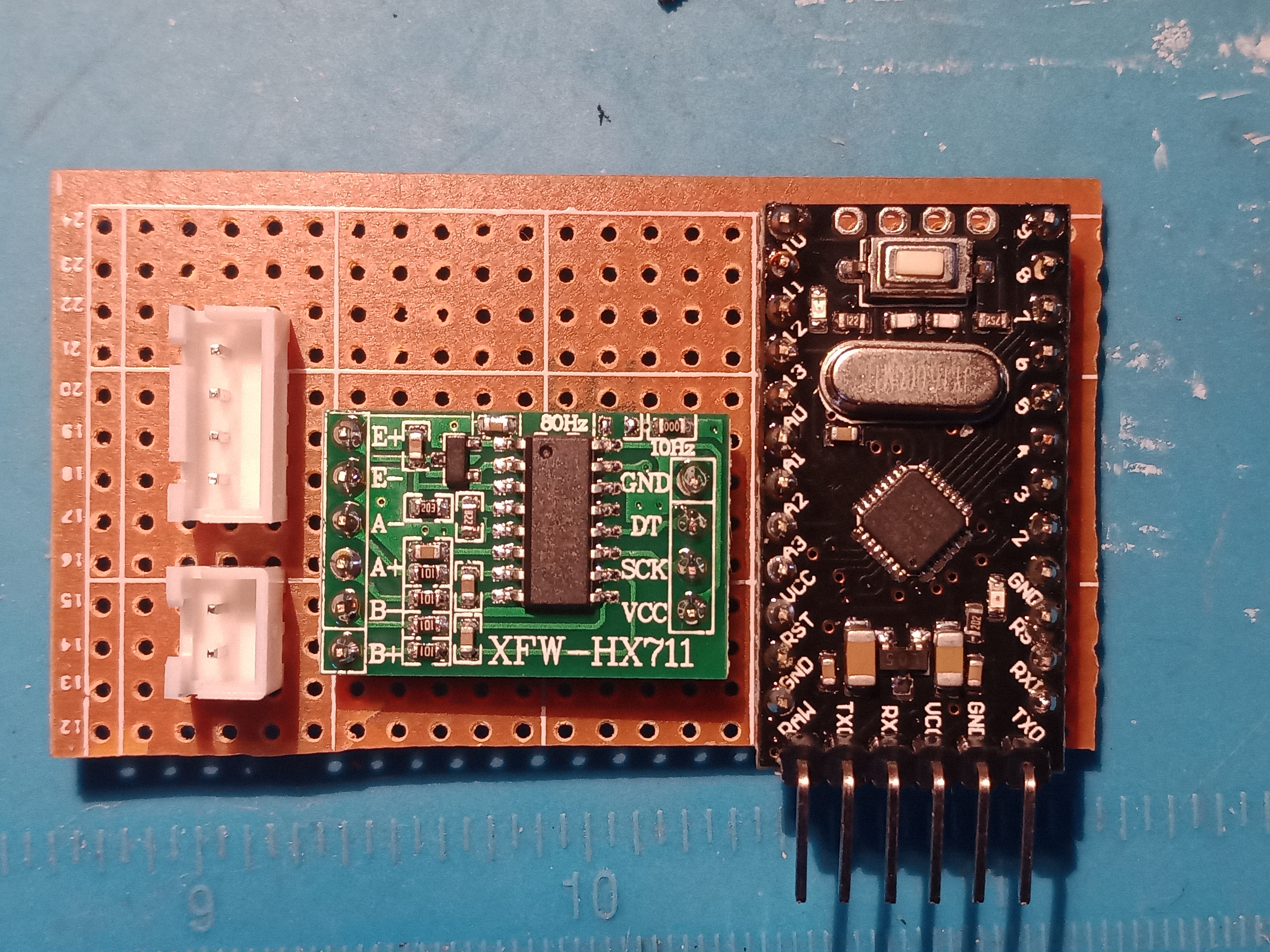
Of course I messed up and had to redo the connections a couple times. (this one is not even the last version)
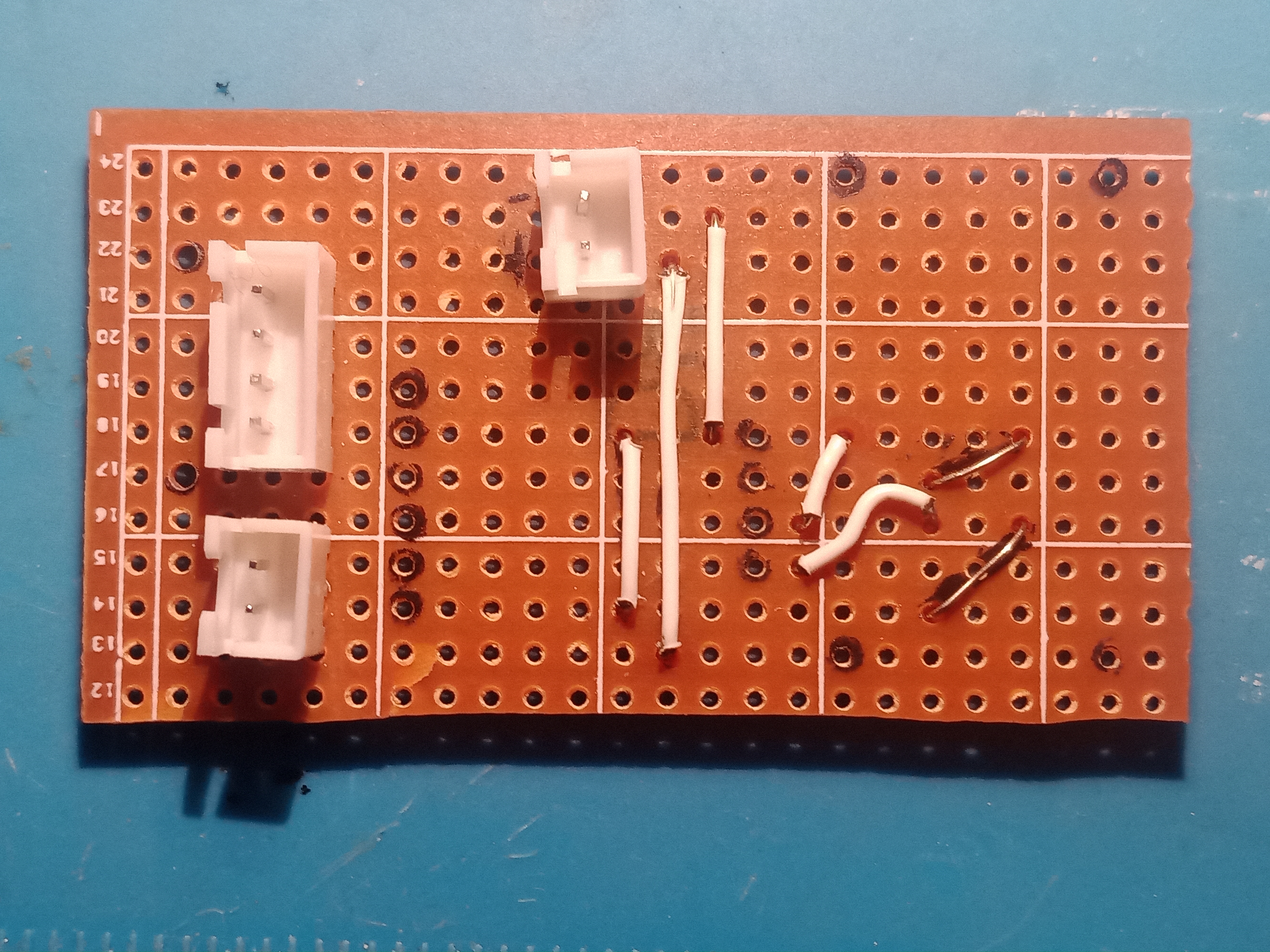
But these two things allowed me to test the idea very conclusively. The alu plate sensor is definitely sensitive enough (applying a few tens of grams on one end while holding the middle is easily detected, even with the B inputs which have only a 32x gain)
So let’s do the real thing !
Building the strain gauge print bed
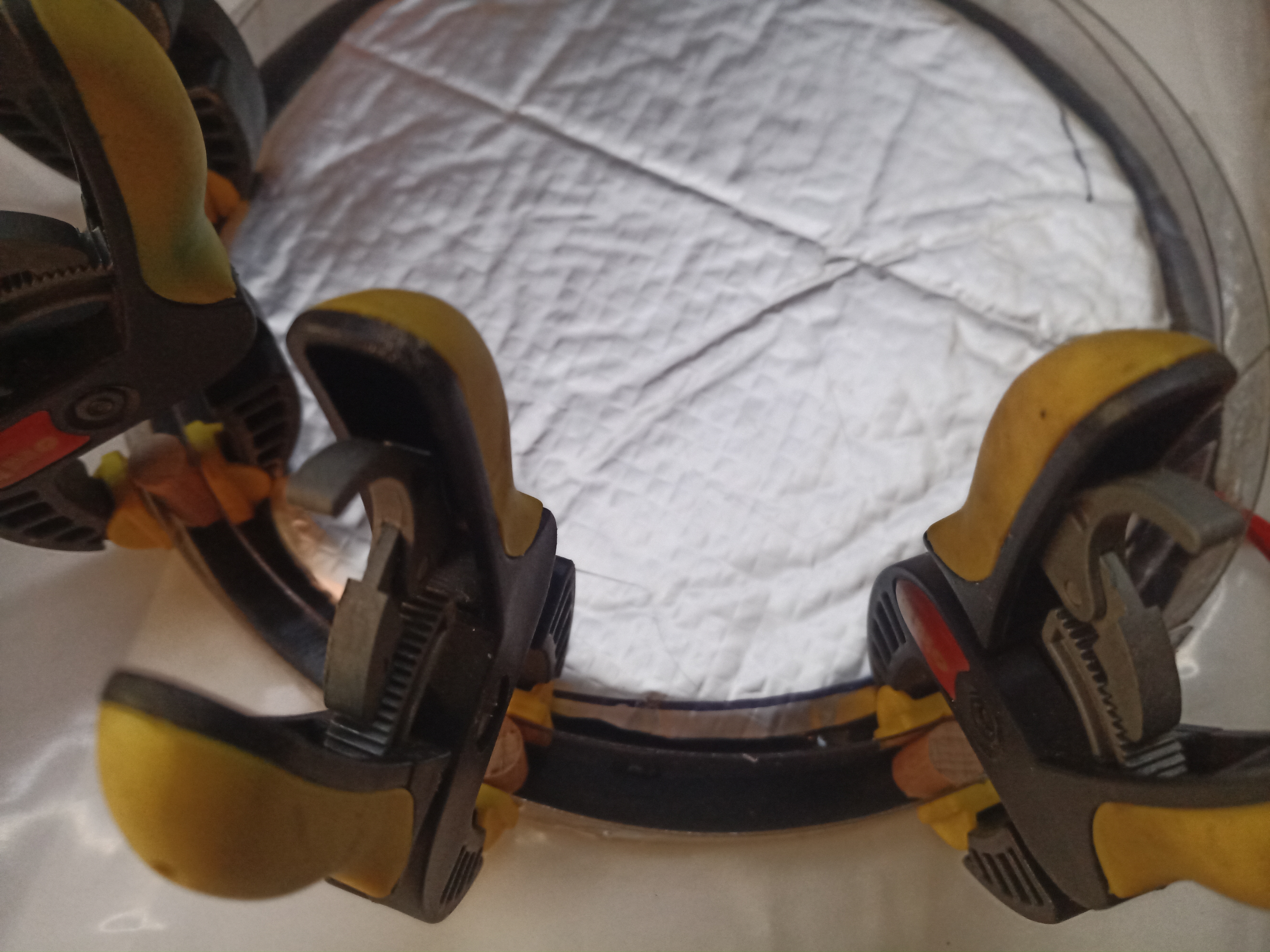
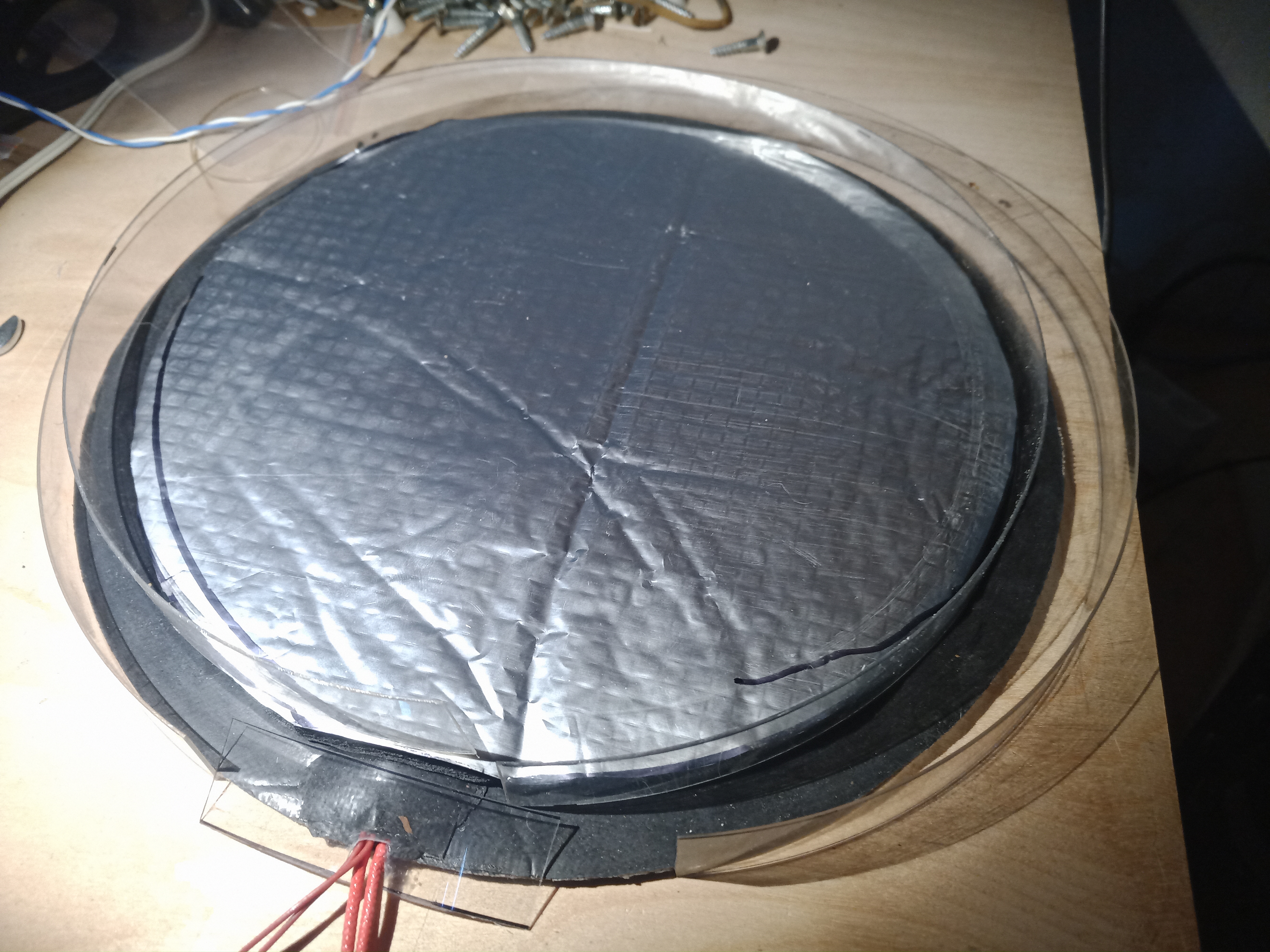
My working print bed is a glass plate, under which a 220V silicone heater is glued. (I did not like all that power going over 12V from the trigorilla kossel controller board, so I switched to a 220V heater switched with an SSR). This works very well. On top of the heater, there is a 12mm insulating neoprene foam backed with aluminum foil. With this, the plate loses very little heat on the backside. I figured the best way to attach the aluminum strain plate would be to glue it to a spacer glued to the glass plate and heater.
Here I create a wall from transparent plastic sheet I had laying around, to mold the spacer
I just hot glued the plastic sheet segments, that gives the finished mold
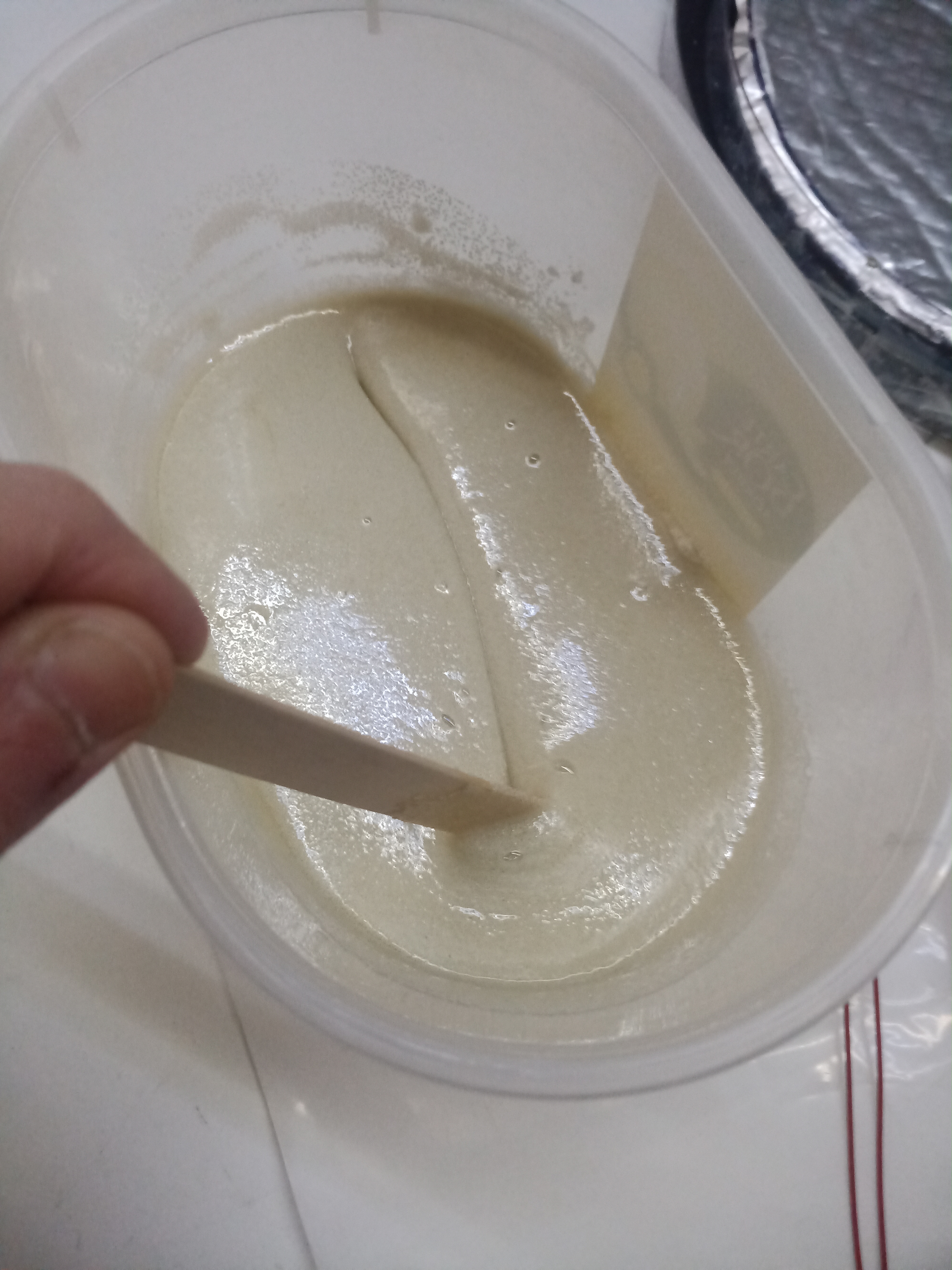
Then poured some mix of glass microsphere (not microballoons, I used 0.3-0.5mm spheres) and epoxy resin. This makes a very rigid, light, insulating composite.
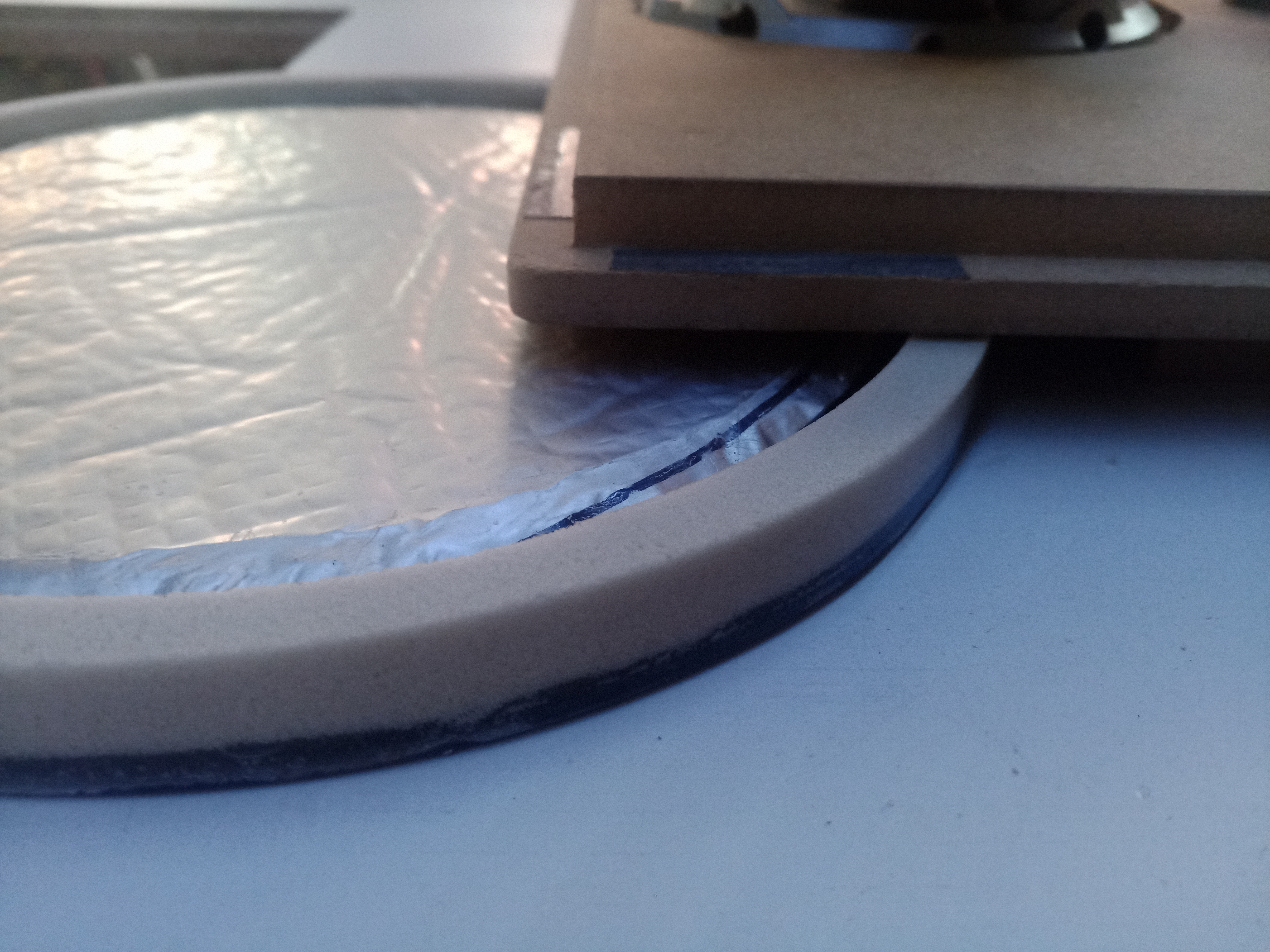
The cured resin has some flashing and raised edges, so I used a quick spacer jig to route flat and level the surface of the spacer
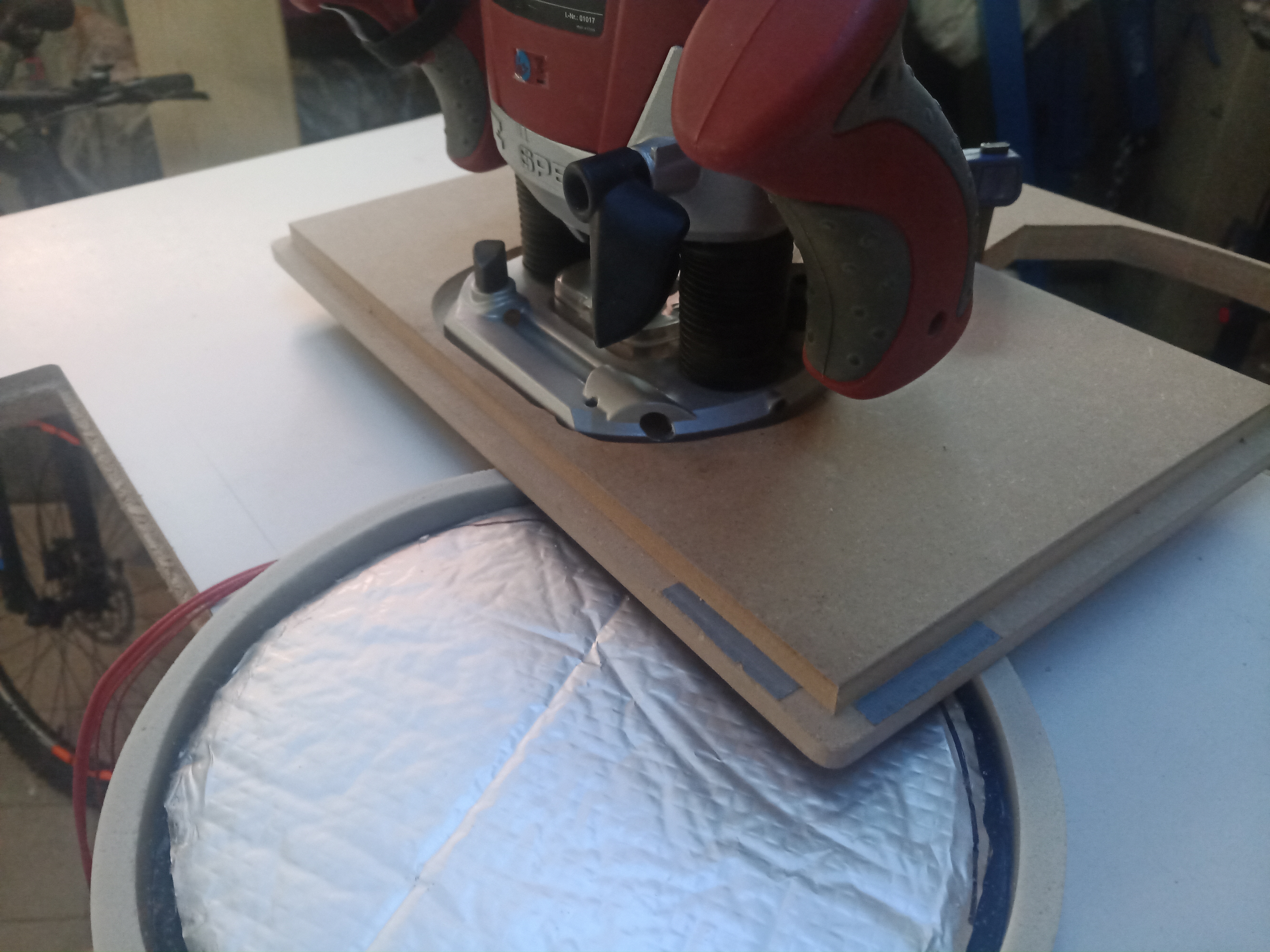
This gives a very flat and smooth surface, perfectly level with the glass print bed
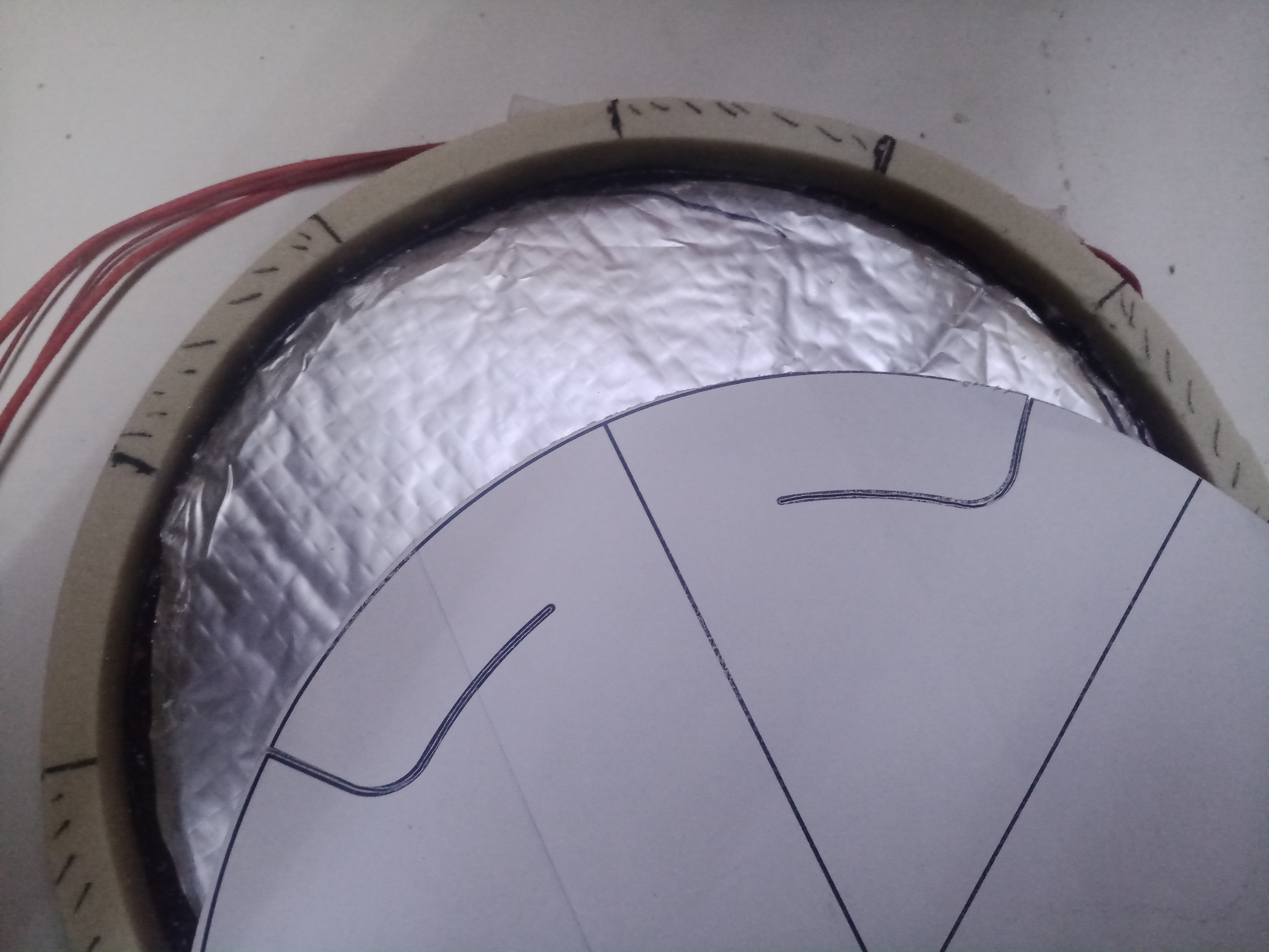
The printbed is held by six little plastic pieces attached to the printer frame. We want the new print bed strain gauge plate to only rest on those 6 pieces. The actual strain sensors are shaped by cutting out fingers/tabs in the aluminum plate (shown here on a paper sawing guide, the L-shapes are the cuts to make). The scrollsaw with a metal blade made quick work of this. To leave a tiny bit of room (0.5mm) for the fingers to flex under pressure (although imperceptible, they do have to flex) I also routed a small clearance on the epoxy spacer, shown here as hatched zones.
Strain gauge wiring and wheatstone bridge
Let’s make a little parenthesis here as I feel the wiring of strain gauges is not really well explained in general. There are plenty of wiring examples of 1, two or more sensors, but I have not found an explanation of how to wire an almost arbitrary number of strain sensors into a single load cell and why.
The usual load cell is made of a parallelogram on which are installed 4 strain gauges, wired in a full wheastone bridge like this:
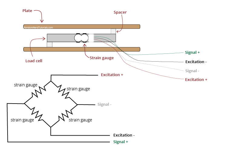
What must be noted is that the strain gauges work in pairs. Always one working in tension, with another working in compression by placing them on opposite sides of the bar under deformation.
So what we really have is this
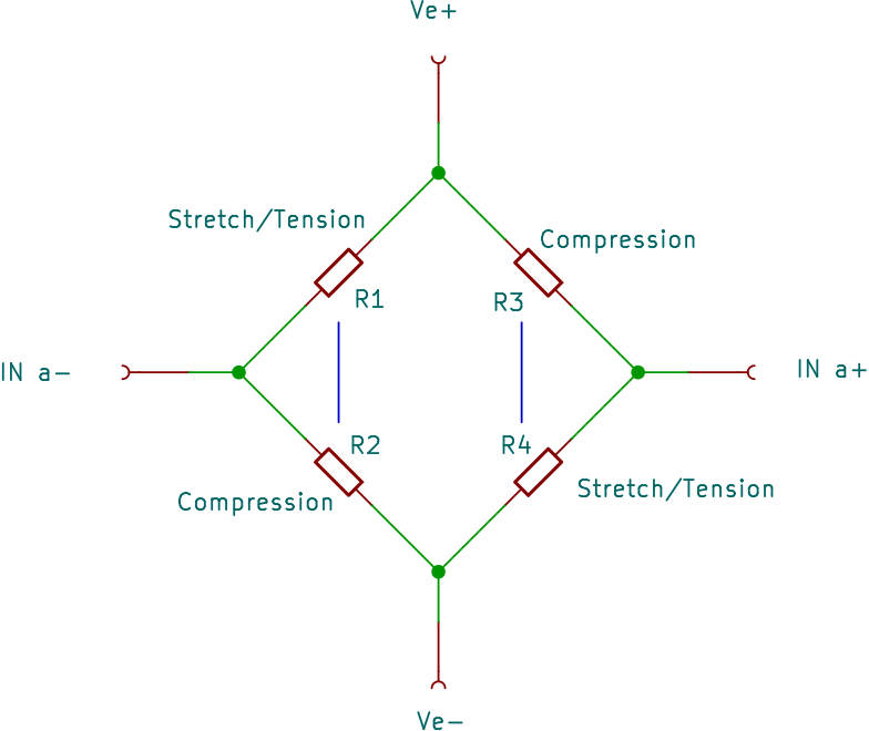
notice the blue lines showing the pairs of resistors/strain gauges. This can be expanded to any number of pairs of strain gauges as long as we keep everything symmetrical by keeping the same number of gauges (resistors here) in each leg of the wheatstone bridge. Here is an example with 8 strain gauges
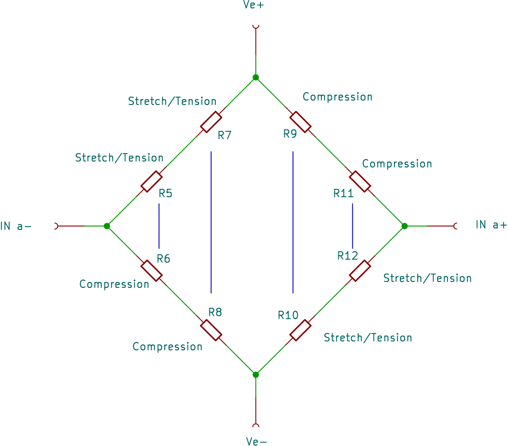
Notice also that in a physical implementation of this wiring, you basically have all sensors wired in a double line of sensors, the end of the lines being the A+/A- points and the middle are the VE+/Ve- points (imagine you pull the circuit by the A+/A- points until they are most spread apart). This makes easy wiring without crossing wires (only one crossing is needed if you want to avoid going all around the whole circuit for one of the connections) In my case, since I have 6 tabs holding the print bed, I will need 6x2 = 12 strain gauges.
Finally there is one last trick: a strain sensor that operates in tension, can be used as a compression sensor on the same surface under tension if it is rotated 90 degrees. Think about it, when you pull on a rubber band, that rubber band narrows as it is stretched. So, we can install pairs of strain sensors all on the same side of the gauge being strained (flexed), no need to use both sides or make holes for passing wires !
Now for the real stuff…
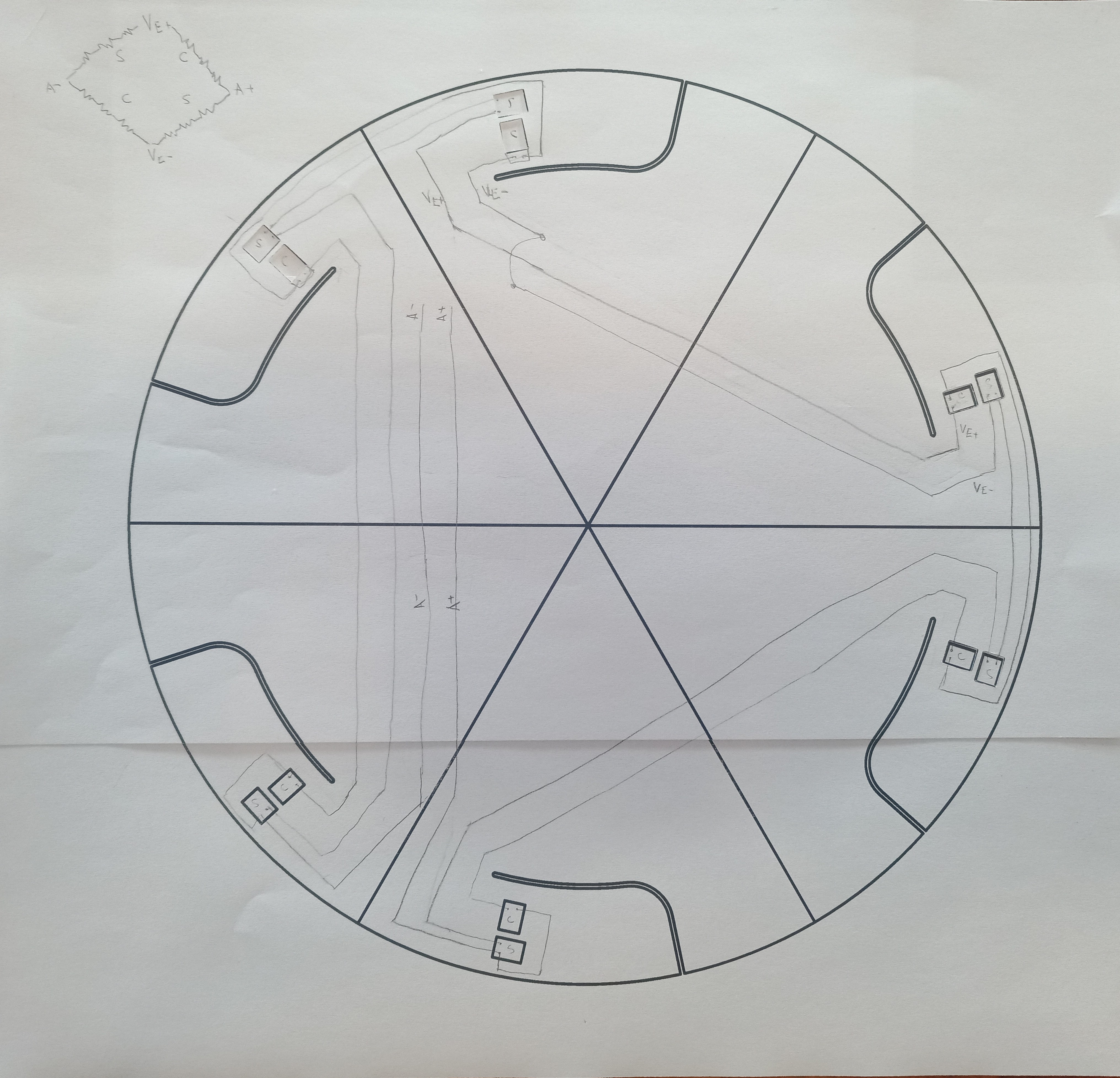
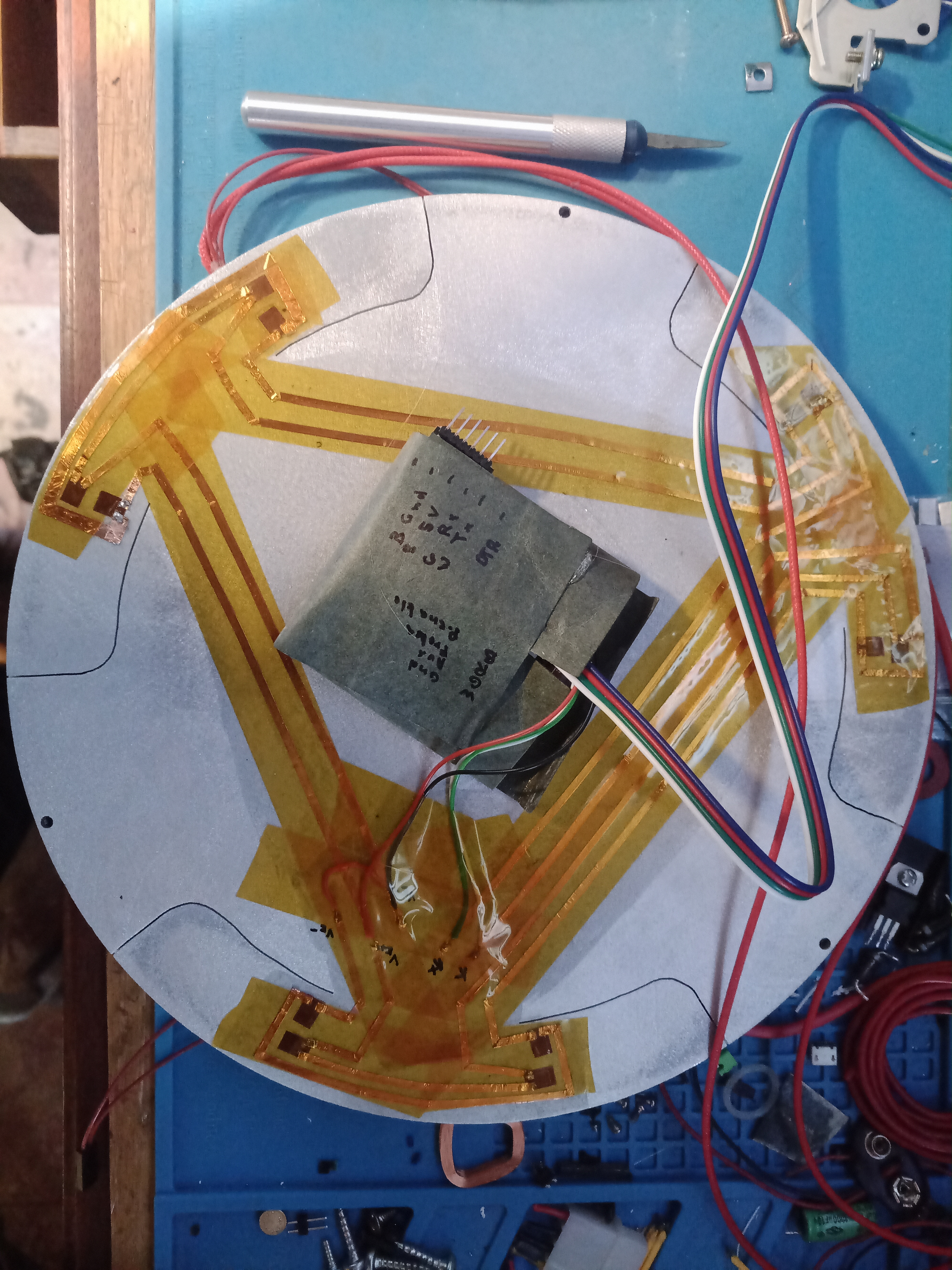
Here is a representation of the wiring, on the plate, with flex fingers cutout. Notice the strain gauges are marked “C” and “S” for compression and stretch respectively.
Remember I said wiring all that thin magnet wire was a pain ? My solution is simple: use copper foil instead. I cut 2mm wide strips of normal EMF shielding copper tape by gluing it to a sheet of paper then using a normal paper cutter. The circuit is then laid out very easily. The connections are made by folding a small (1mm) length of copper tape over itself, tinning the end, then just pressing with the soldering iron on the strain gauge solder pad. Copper foil glue is conductive so it would make contact by itself without soldering but I feel it would not be a permanent or reliable contact. It also probably would induce small variations in the resistance of the contact which we want to avoid since the resistances measured in the strain gauges is already extremely small.
Of course before doing all this wiring, I laid a layer of epoxy to electrically insulate the whole aluminum plate.
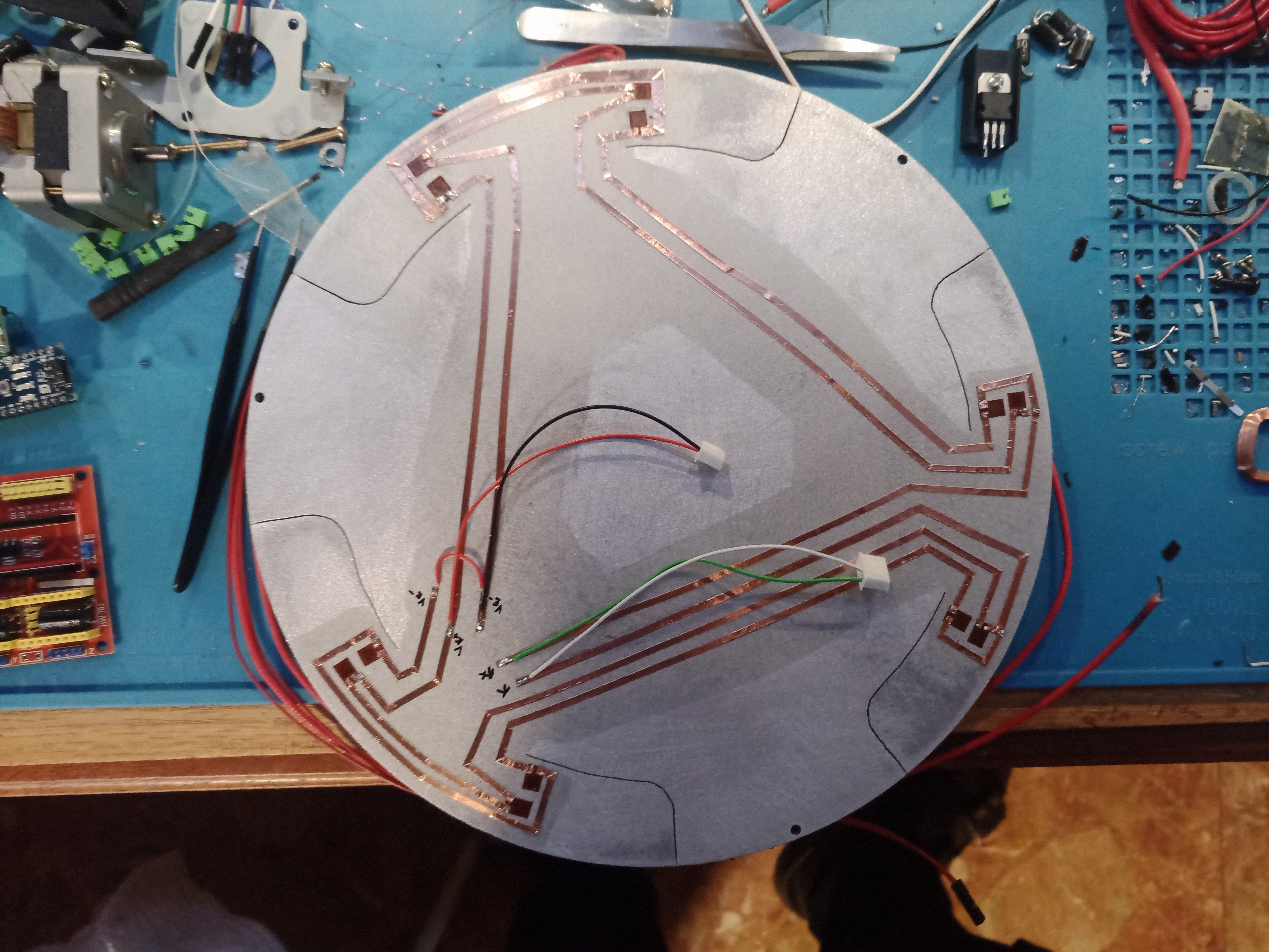
And finally some kapton tape to insulate and protect the tracks, and a very ghetto-like case for the arduino, made from folded insulating cardboard (well obviously the printer is not able to print anything while I do all these modifications…)
The firmware for the arduino is in this github repository, including the HX711 library that I used. I only made a small modification to the lib, by changing the sample number to 2. It’s very quick and dirty code but it allows to do everything required. To configure the arduino after flashing it, connect the serial line and configure your terminal emulator to use 57600 b/s. Then hit return and you will be greeted with a list of available one letter commands. First thing to do is to calibrate the sensors so the values are expressed in grams, then set a threshold weight at which the PROBE output is raised.
As described in the source code, the wiring is very simple. There is a probe connection and an enable. Probe events are generated only when enabled, and a tare operation (zeroing the sensors) is automatically done when the probe is enabled.
The printer firmware needs updating, in my case I use Marlin on a trigorilla 1.4 controller board so I needed to configure the following:
- #define NOZZLE_AS_PROBE
- #define NOZZLE_TO_PROBE_OFFSET { 0, 0, 0 }
- #define PROBE_ENABLE_DISABLE
- #define PROBE_ENABLE_PIN 43
Oh, fun thing about that pin 43: initially my arduino was not being enabled by Marlin when initiating a probe action. Eventually I figured that on the trigorilla 1.4 board I have, the extra pins 42 and 43 are labelled wrong on the board silkscreen. They are reversed. Ah those chinese…
The full Marlin Configuration.h and Configuration_adv.h files are in this branch of my Marlin fork
Conclusion
This works really really well. It is fast. When the nozzle touches the bed during a probe move, the controller triggers as soon as it sees a 40g equivalent on the bed (can be configured of course) but by the time marlin processes the input, the pressure on the print bed is 200g already. The probe and interface are much faster than the physical moves of the printer head. Still, it does not move the bed at all. The small 0.5mm relief for the strain fingers is never bottomed out. In normal operation there is no visible flex at all. It actually takes more than 5Kg on the print bed to really compress that relief space, so there is quite a margin, it’s not like the print bed is bouncing or moving around, it is rock solid. I was afraid the underside of the printbed would heat as now the whole heater is enclosed, but actually the bottom aluminum plate stays cold even after many hours print jobs. The insulating neoprene and foil work really well, all the heat is reflected upwards where we want it.
I think all the requirements I listed are fully met. Calibration is fast and fully automatic, I can change the nozzle or hotend and calibration will run automatically without any special consideration. Marlin UBL leveling using full printbed mapping works really well. I now incorporated a 3 point probe in the preamble g-code generated by Cura, so every print gets proper bed calibration. No matter the temperature or if the printer was moved or something else, prints have perfect first layer everytime and it adds about 45 seconds to the print time. I used to always have to coat the printbed with glue stick in order to have good adhesion, now I can get away with no glue at all most of the times. Only very specific parts with warp-prone shapes, or highly warping materials still require glue. Standard PLA is just fine without.
Bonus: I can know exactly the mass of a print once it is finished :-)
Many lessons learned here. For my next build I will use a different wiring system (either some printable ink or direct etching of track). Actually, this whole sensor, wiring and controller could be made on an aluminum PCB, as a single part. The molding process was a bit tedious because the glass bed was entirely covered by the heater. A better sized heater pad, with a small margin free around would have made things a lot easier. The other issue I had was with passing the heater cables through the spacer, that was leaking a bit while molding. Also, at some point I was pulling my hair trying to find why Marlin would go into emergency stop mode immediately when the nozzle touched the bed and triggered. Turns out, if your tower height (for delta) is very wrong (like 10cm off but maybe less), Marlin completely panics when it gets a probe triggered where it thinks the bed should not be. Which kind of makes sense but I was not expecting my Marlin config to be wrong and kept searching for the cause in my strain gauge sensors and firmware…
Also, I should stop trying to make quick veroboard circuits except for the very simplest ones. I always end up spending as much time as if I had designed it properly in kicad and etched it. Which BTW is soon going to be even faster once I finish my UV laser printer to directly expose PCBs. Hopefully soon a new blog entry about that project!
Update: here is a quick demonstration of the Z-Probing. If you wonder what the strange wrinkly black thing is, read my remote hotend fan, part one and part two

Comments
Mike Simpson
I really enjoyed your article on “The Ultimate 3D Printer Z Probe.” The idea of weighing the print during the process is fascinating and one I haven’t come across before.
However, there’s an important aspect I’d like to highlight: under-bed sensors can sometimes face serious issues due to the dynamic behavior of the bed itself. Additionally, sensor mismatches can contribute to complications. I want to clarify that I don’t anticipate any problems with strain gauge sensors on a delta printer with a heavy bed. But if you’re using a lighter square bed, like those found on bed slingers, it could present challenges.
The core of the issue arises when the nozzle makes contact with the bed, transmitting a transverse (up and down) pressure wave to the sensors. Under certain conditions, this wave may reflect off the edges and corners, and occasionally, these reflections can cancel each other out.
I initiated a discussion on this topic over on https://reprap.org/forum/read.php?424,865620. In my own setups, I utilize a single under-bed piezo sensor to determine the nozzle contact position—essentially acting as a Z stop—paired with a touch sensor for bed mapping. You can check them out at https://www.youtube.com/watch?v=DQXM4nrcsr4 and https://www.youtube.com/watch?v=waXIr_ytukw. My touch sensors are custom designed, having a sensitivity of under 1 gram and a repeatability within 2 microns.
Bruno
Hi, thanks for the comment ! I understand your point if you want ultra-high precision using piezo, I think they introduce some issues that strain sensors do not have. Consider also that all my 12 strain sensors are part of a single wheatstone bridge. There is no sensor mismatch, everything is averaged out. As far as dynamic effects, I have no levers, hinges, spring or cantilevers, everything rests on 4mm thick x25mm wide aluminium fingers, part of a single plate. And the bed itself is glass, thus extremely rigid. As far as precision, the strain sensors give me a resolution in the 1/100 gram if desired, but in practice it is a bit noisy and not required to detect contact reliably. With that said your work on quantifying the touch height error is interesting, I may try doing that too and see how well (or bad) the strain sensor printed fares.
Jacqui
This post is very detailed and useful. I like how it explains the setup in a clear way for people interested in 3D printing.
Leave a comment
Your email address will not be published. Required fields are marked *