Brushless fan PWM to 5VDC interface
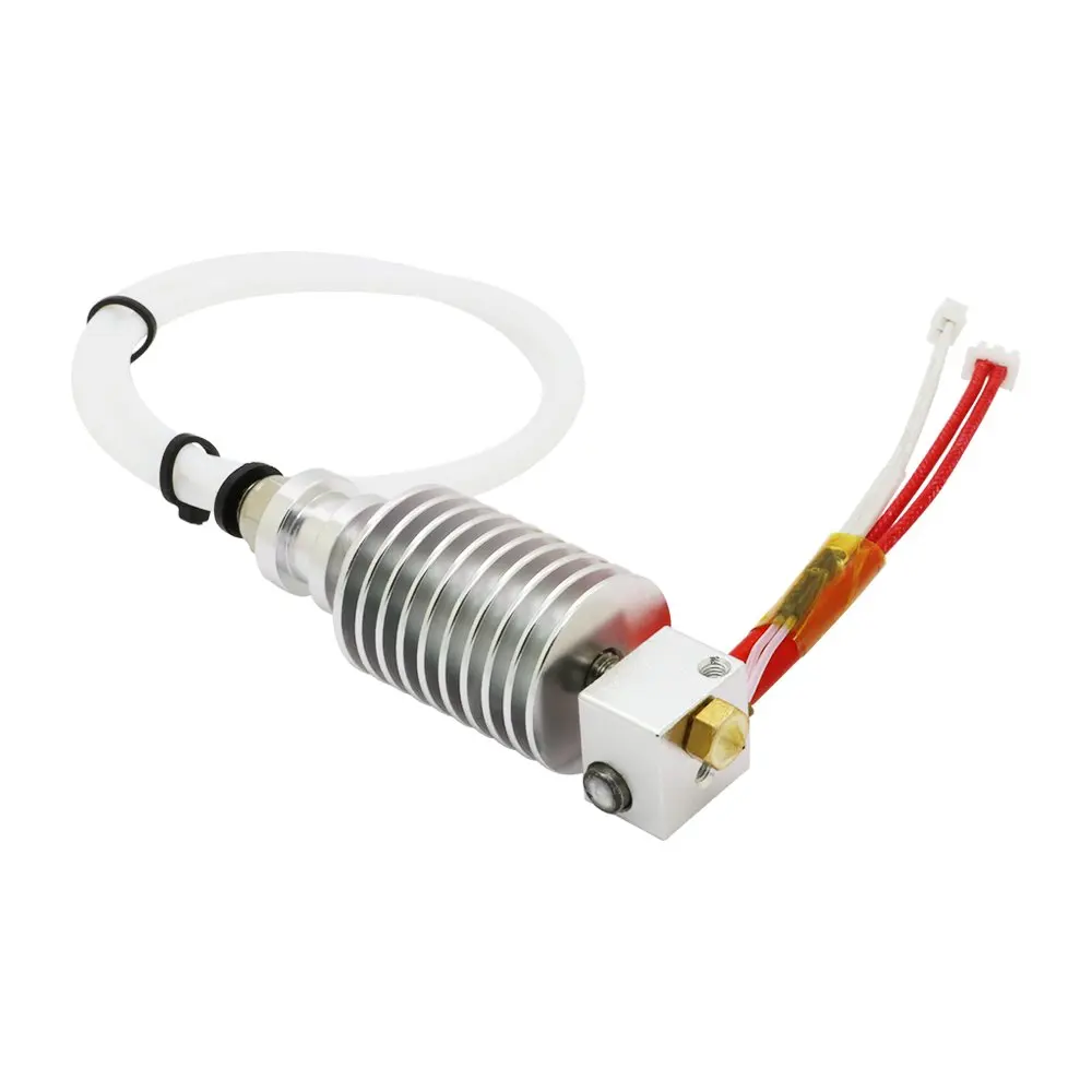
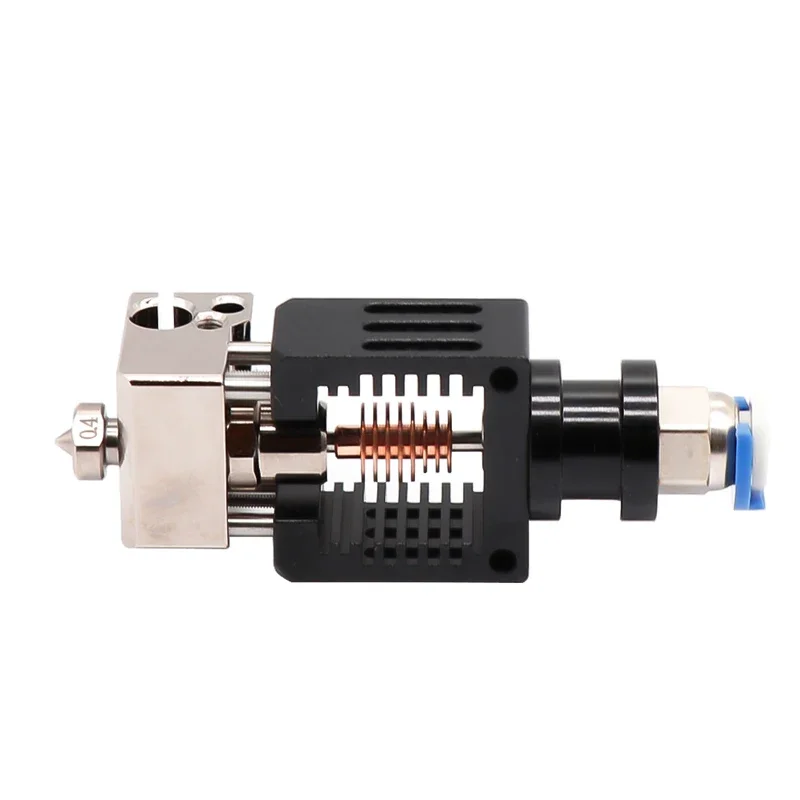
The Anycubic Kossel printer came with a J5 type hotend, which is heavy, big, and just not really good. The flow rate is rather bad. I changed it with a mozzie mq hotend which promised higher flow rate and is much more compact and light. Pretty drastic difference between the two. As a reference, the copper radiator of the mozzie is about 10mm diameter by 15mm long, while the aluminum radiator of the J5 is 25x35mm.
J5 on left, Mozzie on right
Unfortunately, I kept having issues with the filament getting stuck in the mozzie hotend. I eventually figured out two main issues: retraction moves were set too big (5mm), this caused some molten filament to be pulled past the heatbreak and get stuck in the cold part of the hotend. The second issue was that the cold part was… not cold enough. Printing would go fine, as long as there was some filament flow. However, if the printer sat hot for too long without extruding, a 5mm section of filament would soften in the cold hotend part and get stuck there. The heat break could not be really at fault, it’s a very thin-walled section of stainless tubing and seemd long enough, providing a good separation between hot and cold end. Therefore, cooling was the issue. I replaced the fan with another with faster flow, but nothing, the issue came up again after just a bit longer. No matter what fan I tried on that hotend, it seemed nothing would cool the cool part enough. And I new for sure this was the issue: if I just blasted the hotend with compressed air every five minutes, the filament would never get stuck.
I finally bit the bullet and decided to move on to something I intended to do anyway eventually, as it will be required for the new remote-direct extruder I am working on. Namely, a remote fan, using a fabric tube or sock to lead the air were it is needed. The original motivation for this was also to be able to lower the mass of the printhead, and provide higher airflow and a quieter bigger fan. As for the quieter fan, the opposite happened but I do not really care as this printer is remote anyway, so noise is not an issue.
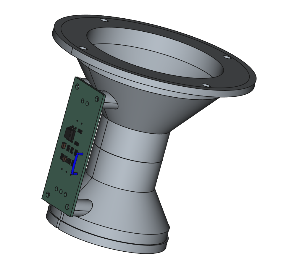
I decided to use this 32mm brushless hairdryer fan, which seemed promising
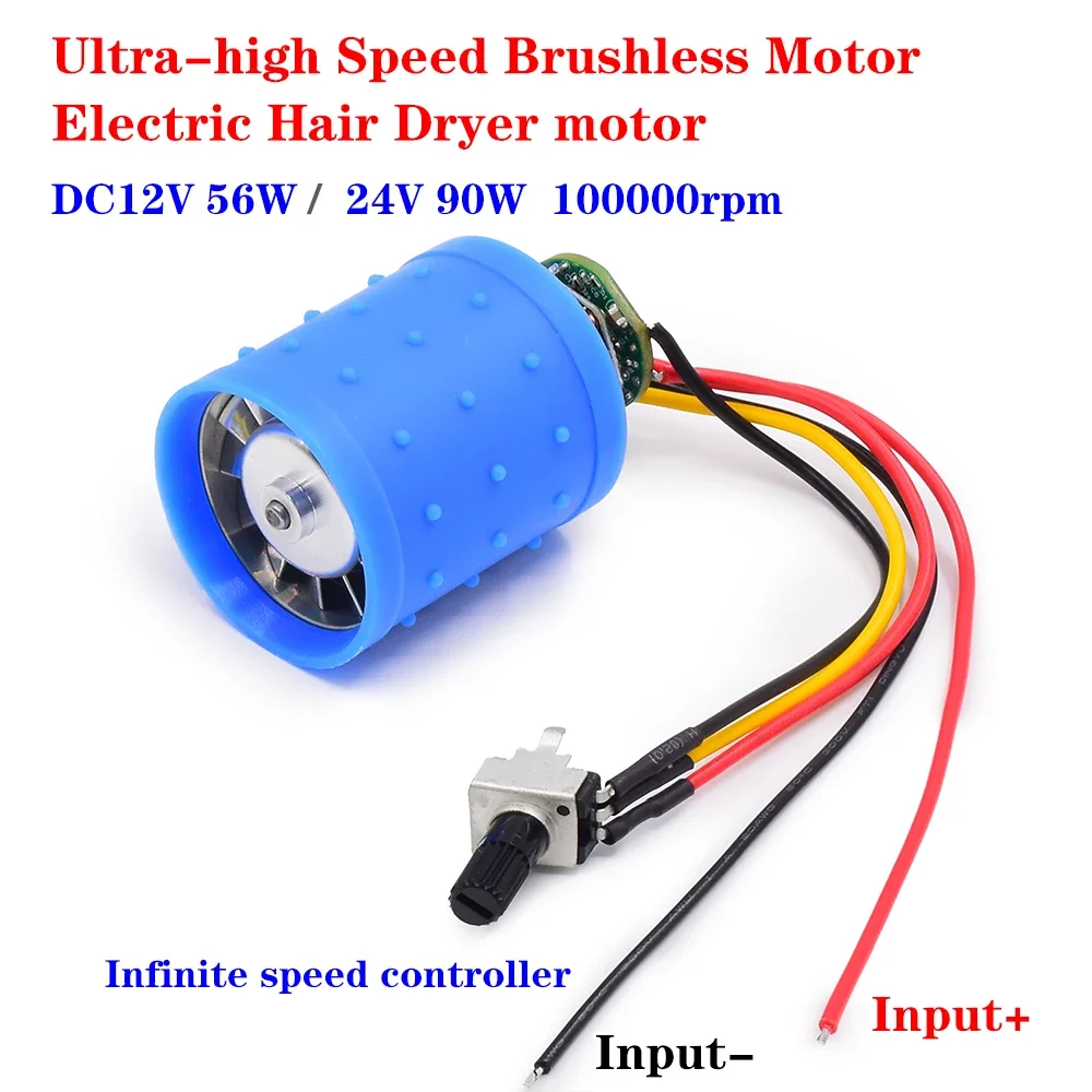
Effectively, it has incredibly high flow. It actually produces significant thrust when running. So much so that it made Marlin shutdown in detecting a thermal runaway. What happened is that the fan cooled so well that the hot end was struggling to keep temperature. Some of the cool air was hitting the hotend so Marlin tried to compensate by running it full on to attempt to maintain temperature.
I solved this by adding a small aluminum sheet on top of the hotend to form a heat shield, and also by not running the fan on full speed. Which brought up the next issue: controlling the fan from Marlin.
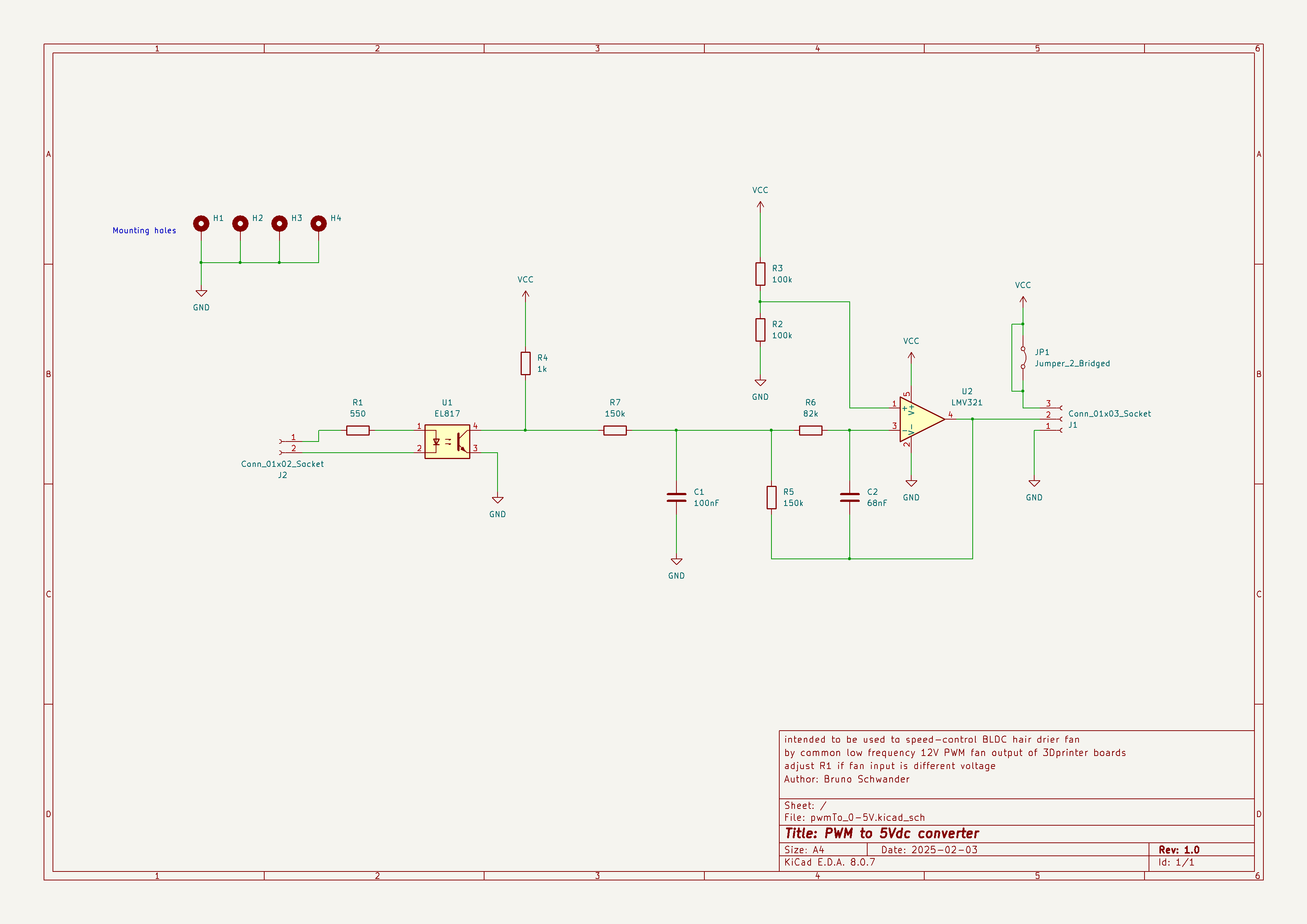
This fan uses a potentiometer to control speed. Testing its terminals showed that the BLDC controller provided 0 and 5V as output to the potentiomer, and the pot wiper as input. Marlin however runs fans on PWM with approximately a 1KHz frequency. An interface is therefore needed, which I designed in the following circuit.
All files are on the github repository
The circuit basically implements a low-pass filter. The response is slow enough that the fan should nicely speed up and down, but still be reactive. It assumes a 12VDC peak PWM varying duty-cycle input signal, with 0% duty cycle turning off the fan and 100% full on. On the output, the signal varies correspondingly between close to 0 V and 5V, the LMV321 Op-Amp being a 5V rail-to-rail part.
I used an optocoupler as I had them in my box of recovered parts and it does not hurt just in case different supplies are used for the control board and the fan power. It also removes any possible voltage mismatch between the input signal and the rest of the circuit. Since the input is assumed to be 12V, if your fans were originally 5V or 24V, the R1 resistor should be adjusted to provide a similar current to the optocoupler diode.
One more tweak: marlin normally uses software PWM for generating the fan signal. Normal fans being low speed and high inertia, that is usually sufficient. However, in this case, it leads to irregular fan speed. This could be fixed two ways: in hardware, by modifying the time constant of the PWM to 5V circuit. An LTspice model of the circuit is also in the git repository to experiment and determine the RC values. Alternatively (and it is the solution I chose because at that point my circuit board was already soldered up…), It is possible to configure Marlin to increase the PWM frequency or use the hardware PWM. The SOFT_PWM and related #defines allow for this.
And that’s it. With these changes the new hotend is very reliable and prints very well.
Leave a comment
Your email address will not be published. Required fields are marked *